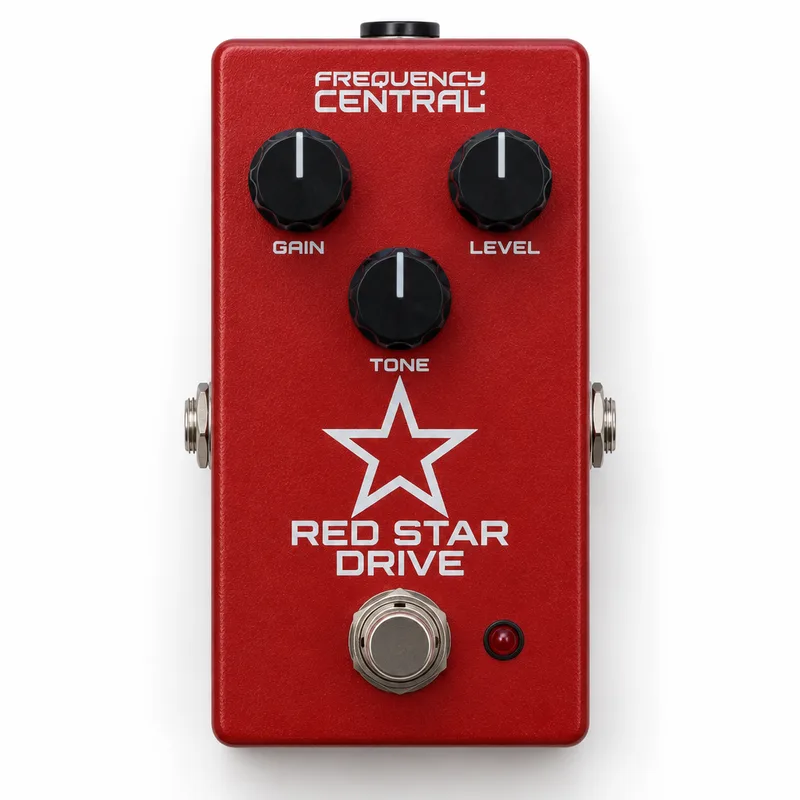
The Frequency Central Red Star Drive is a booster/overdrive pedal built around a submini tube that replaces the transistor you would find in a conventional drive circuit. It is described as a very light drive, so it sits at the gentle end of the overdrive family, closer in feel to a boost than to a heavy distortion pedal1.
The circuit was created by Frequency Central, who posted the schematic over at DIYSB, the DIY stompboxes forum. The stripboard layout published on Guitar FX Layouts was built and verified by members of that community1.
Power and what the tube means for your build
The pedal runs on +12V. The layout's author warns builders to make sure components are rated at least 25V because of the +12V operation1.
This circuit is designed around a +12V rail, not the lower voltages most pedalboard supplies deliver. If you build or power one, the supply and components need to handle +12V, with parts rated at least 25V1.
The two versions
The Red Star Drive exists in two versions, and the difference between them comes down to the clipping diodes1:
Both versions were verified as working builds, since the only real difference is the diodes1. Version 2 was additionally verified with a Tung-Sol 5672 submini tube1.
Where it came from
The Red Star Drive comes from Frequency Central, who posted the schematic at DIYSB. The Guitar FX Layouts project page turned that schematic into a verified stripboard layout, and build reports followed from the community, with both versions verified, the only real difference being the diodes1.
Questions
What is the difference between the two Red Star Drive versions?
Version 1 uses symmetrical clipping diodes and Version 2 uses asymmetrical clipping diodes. According to the Guitar FX Layouts thread, that is the only real difference between the two circuits, and both versions were verified as working builds. Version 2 was also verified with a Tung-Sol 5672 tube.
What kind of tube does the Red Star Drive use?
The Red Star Drive uses a submini tube in place of the transistor found in a conventional drive circuit. In the verified build reports on Guitar FX Layouts, Version 2 was confirmed working with a Tung-Sol 5672 submini tube.
Where does the Red Star Drive circuit come from?
The circuit was created by Frequency Central, who posted the schematic over at DIYSB, the DIY stompboxes forum. The Guitar FX Layouts project page published a verified stripboard layout built from that schematic.
Is the Red Star Drive a boost or an overdrive?
It is described as a booster/overdrive, and the drive character is described as very light. Players who want a gentle push rather than heavy clipping would place it toward the boost end of the drive family.
Sources (1)
- Guitar FX Layouts: Frequency Central Red Star Drive, Guitar FX Layouts (tagboardeffects.blogspot.com), 2017-02-21