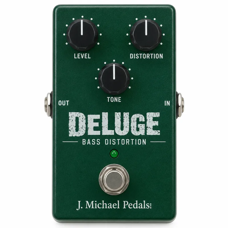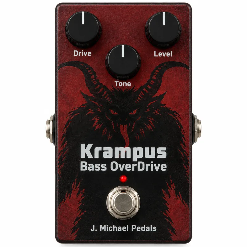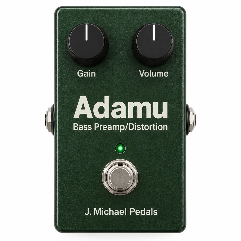

The Adamu Bass Preamp/Distortion is a bass preamp and distortion DIY project by J. Michael Pedals, sold through General Guitar Gadgets. It is not a finished pedal: General Guitar Gadgets describes it as "an awesome bass preamp and distortion by J. Michael Pedals," offered as a kit built around a Ready-to-Solder Printed Circuit Board. The circuit is based on the DOD 250 ('77 Gray) Guitar Distortion, but tuned for bass1. It sits in the wider family of preamp pedals and distortion pedals designed for bass, alongside other J. Michael Pedals projects such as the Krampus Bass OverDrive and the Deluge Bass Distortion.
Circuit and controls
The heart of the circuit is a TL071 opamp. Clipping is done by two red LEDs, D1 and D2, in the distortion stage, and a separate status indicator LED and holder (D4) shows when the effect is engaged1.
| Control / part | Reference | Value and type |
|---|---|---|
| Gain | R7 | 500k, reverse log taper potentiometer |
| Volume | R10 | 100k, log (audio) taper potentiometer |
| Clipping | D1, D2 | Red LEDs |
| Status indicator | D4 | LED and holder |
| Foot switch | Sw1 | Heavy duty 3PDT |
The Gain control's reverse log taper means most of its sweep happens early in the turn, which is a common choice for distortion gain stages. The Volume control uses a standard audio taper1.
Power and connections
The project runs from a 9 volt battery (B1), which is not included in the kit. Connections are wired to three jacks and a DC jack on the board1.
| Connection | Reference | Type |
|---|---|---|
| Input | J1 | Stereo quarter-inch jack |
| Output | J2 | Mono quarter-inch jack |
| Power | J3 | DC jack |
The stereo input jack is the usual DIY arrangement for battery switching: the battery connects only when a plug is inserted. A heavy duty 3PDT foot switch (Sw1) handles true bypass wiring, and the status indicator LED and holder (D4) mount in the enclosure1.
Versions and board options
The Adamu Bass Preamp/Distortion project documentation lists several optional parts that shape how the board can be populated. An optional D8 diode position accepts a 1N4001 or 1N914, an optional R4 resistor can be fitted at a value of 47k with the instructions giving details, and an optional C8 capacitor position takes a 100µF aluminum electrolytic1.
If you are building on the PCB marked "DIST2", use the DIST2 project files; the earlier PCB marked "DIST" has its own set of files. Check which board you have before ordering parts.
Several parts on the bill of materials are optional, and the build instructions give the details of when to fit them1:
- R12 (optional): 100 ohm resistor
- D8 (optional): 1N4001 or 1N914 diode
- R4 (optional value): 47k, an optional value covered in the instructions
- C8 (optional): 100µF aluminum electrolytic capacitor
Videos
J. Michael Pedals
Questions
Is the Adamu a finished pedal or a DIY kit?
It is a DIY project, not a finished pedal. General Guitar Gadgets sells it as a kit that includes the Ready-to-Solder Printed Circuit Board (RTS PCB). You supply the enclosure work, soldering and assembly, and the 9 volt battery is not included in the kit.
Which circuit is the Adamu based on?
General Guitar Gadgets describes the Adamu as based on the DOD 250 ('77 Grey) Guitar Distortion, but tuned for bass. The circuit uses a TL071 opamp at IC1, with Gain on a 500k reverse log taper pot and Volume on a 100k audio taper pot.
What clipping does the Adamu use?
The circuit clips with two red LEDs, listed as D1 and D2 on the bill of materials. An optional D8 diode, a 1N4001 or 1N914, can also be fitted, and the build instructions cover the details of optional parts.
Where can I find the Adamu build instructions?
General Guitar Gadgets publishes a schematic PDF for the DIST2 PCB on the Adamu project page, along with project files for both the PCB marked DIST2 and the earlier PCB marked DIST. The bill of materials document is dated version 2019February25.
Sources (1)
- Adamu Bass Preamp/Distortion: DIY Kit & Schematic, General Guitar Gadgets, 2014-07-13