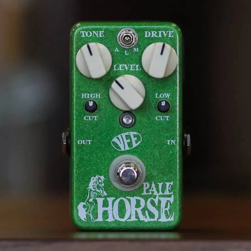


The VFE Pale Horse is an overdrive pedal that now exists as a DIY project: a set of printed circuit boards for builders to assemble themselves. The PCBs are the actual boards used to build the recently discontinued line of VFE pedals, provided for DIY use only1. VFE describes the result as a "unique and wide-ranging overdrive that can cover a lot of bases!"1
Each VFE project, the Pale Horse included, has two PCBs: an audio board and a switching board, wired together to form the complete circuit2. The audio PCB measures 2.17" x 2.025"1.
The Pale Horse is a DIY pedal project: the PCBs are the actual boards used to build the recently discontinued line of VFE pedals and are provided for DIY use only1.
The controls and internal trimmers
The Pale Horse carries external pots for drive, tone and level, plus a LOW control and a COMP control, and hides two trimmers inside for tweaking the input impedance and the frequency center of the tone pot2.
| Control | What it does |
|---|---|
| TONE | Active boost/cut of frequencies above the threshold set by the internal FREQ trimpot. Stock setting at 3.2kHz1 |
| FREQ | Internal trimpot to make the tone control a treble boost/cut, or higher up like a presence boost/cut. Stock setting about 1/4 up1 |
| IMPEDANCE | Sets the input impedance via an internal trimpot. Lower impedances respond more dynamically to the guitar's volume knob; higher impedances add sparkle to the top end1 |
| LOW | Pre-gain bass cut to tighten up the bottom end, or turn it up for a thicker, full-range drive. Makes the Pale Horse a bass-friendly overdrive1 |
| COMP | Uses Variable HCC technology to transition between a sweet, asymmetrical drive tone (counterclockwise) and a dynamic mosfet drive (clockwise). The 12:00 center-detent position locks in clean boost mode1 |
The COMP control is the unusual one. Instead of a simple gain knob, it moves between two clipping characters, with a center detent that gives a clean boost. The pot itself is a 1M pot with a W taper and center detent1.
A few component details matter to builders:
- The DRIVE pot is a 1MA pot with 10% tolerance instead of the usual 20%1.
- The 10kA level pot labeled on the PCB is actually 50kA1.
- The 2n5484 or J113 transistor must be used for proper operation1.
- The build calls for a 10uF bi-polar electrolytic capacitor2.
One builder documented that a J112 substitution, even though very close in spec to the J113, caused a sputtered output from the gain stage and did not work correctly in this circuit2.
Optional socketed mod resistors
The PCB includes two optional socketed resistor positions. The *100k sets the lowest input impedance value of the OPA2134 when the IMPEDANCE trimmer is turned all the way down; 100k was found to be a good overall value. The *1M sets a high impedance input on the tone section and/or rolls off some subs, but the author found it was not needed on their build1.
Power: split rail, plus and minus 9V
The Pale Horse uses a split rail, +9V and -9V, for operation2. The VFE documentation describes the same thing as a split-rail supply1. This is not the single 9V supply most pedals run on: the circuit generates both a positive and a negative rail from the input.
Before inserting the IC, the build guide's author confirms ground continuity between the two boards, -9V on pin 4 and +9 on pin 8 of the IC2. In one documented build powered by a 9.42V One Spot, the measured readings were:
| Test point | Reading |
|---|---|
| IC pin 4 | -8.18V |
| IC pin 8 | 8.64V |
| 2n5484 source | -8.18V |
| 2n5484 gate | -8.18V |
All readings were taken with the pedal powered by a 9.42V One Spot supply1.
Building the Pale Horse from the DIY PCBs
The madbeanpedals build guide shows most of the process of building one of the VFE projects3. The build uses 16mm pots mounted on the enclosure and then soldered to the PCB; 9mm pots can be substituted but should be checked for clearance with the drill holes2. The trimmers are Bourns 3362p, which the guide's author used in all their builds2.
A few assembly notes from the build guide:
- The 2n5484 transistor can be socketed rather than soldered directly2.
- The LED indicator is left unsoldered until final assembly: load it loose into the PCB, assemble the pedal with all the pots and jacks screwed down, then solder it directly to the board2.
- The author used two 4u7 BP caps in parallel in place of the 10uF BP12.
On the LOW control and bass response, the build guide notes that with only a 4u7 cap, when the Fat control is turned all the way up, the corner frequency of the added bass would be around 68Hz2.
Videos
ProGuitarShopDemos
Mike Hermans
JetCityMusic
Questions
Can I sell a Pale Horse I built from VFE PCBs?
No. The VFE projects hosted on madbeanpedals are licensed for DIY use only and may not be used in any commercial endeavor, including the sale of completed pedals or kits. A Pale Horse you build is for your own pedalboard, not for resale.
What does the FREQ trimpot do on the Pale Horse?
FREQ is an internal trimpot that sets the frequency threshold the TONE control works above. Turned low, the tone control acts as a treble boost/cut; turned higher, it works more like a presence boost/cut. The stock setting is about a quarter of the way up, with the TONE threshold at 3.2kHz.
Is the VFE Pale Horse discontinued?
Yes. The Pale Horse was part of a line of VFE pedals that was discontinued, and the PCBs were later provided for DIY use only through madbeanpedals. VFE Pedals has also stated it will close down at the end of 2026, while continuing repair service indefinitely.
What voltages should the Pale Horse IC pins read?
Before inserting the IC, check that you have ground continuity between the two boards, -9V on pin 4 and +9V on pin 8. One documented build, powered by a 9.42V One Spot, measured -8.18V on pin 4, 8.64V on pin 8, and -8.18V on the 2n5484 source and gate.
Sources (3)
- Microsoft Word, Madbean Pedals, 2017-07-31
- Microsoft Word, madbeanpedals.com, 2017-11
- Microsoft Word, madbeanpedals.com, 2017-11